Electrical safety
Hardwired alarm installation involves building wiring and may require a qualified electrician under local law. Follow the exact alarm wiring diagram and applicable electrical/fire codes; do not improvise conductor connections.
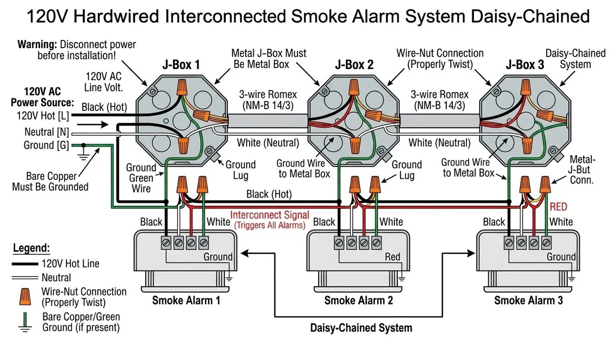
Hardwired smoke alarms connect to 120V (or 240V) building AC power using a 3-wire harness: Black (Line/Hot), White (Neutral), and Red or Orange (Interconnect traveler). Always shut off the circuit breaker before handling wiring, and connect matching wire colors using UL-listed wire nuts.
NFPA 72 Spatial Clearance & Layout Rules
Wiring Connection Steps:
1. Shut off Breaker: Verify zero voltage at junction box with non-contact tester.
2. Mount Bracket: Secure mounting plate to ceiling electrical junction box.
3. Connect Harness: Black to Black (Hot), White to White (Neutral), Red to Red/Yellow (Interconnect).
4. Plug & Test: Snap wiring harness into alarm, attach to bracket, restore power, test horn.
Hardwired smoke alarms provide reliable mains electrical power backed by emergency batteries, with an interconnect signaling line that activates all alarms simultaneously during a fire.
Standard Wire Color Code Reference
| Wire Color |
Function |
Connection Instructions |
| Black |
120V AC Line (Hot) |
Connects to black building power conductor with wire nut |
| White |
AC Neutral |
Connects to white building neutral conductor with wire nut |
| Red or Orange |
Interconnect Traveler (9V DC logic) |
Connects to red traveler wire linking all alarms together |
| Bare Copper / Green |
Equipment Ground |
Connects to metal junction box grounding screw (alarm casing is double-insulated) |
Important Safety Guideline
Mains AC voltage can cause severe electrical shock or electrocution. If you are unfamiliar with residential wiring, hire a licensed electrician.