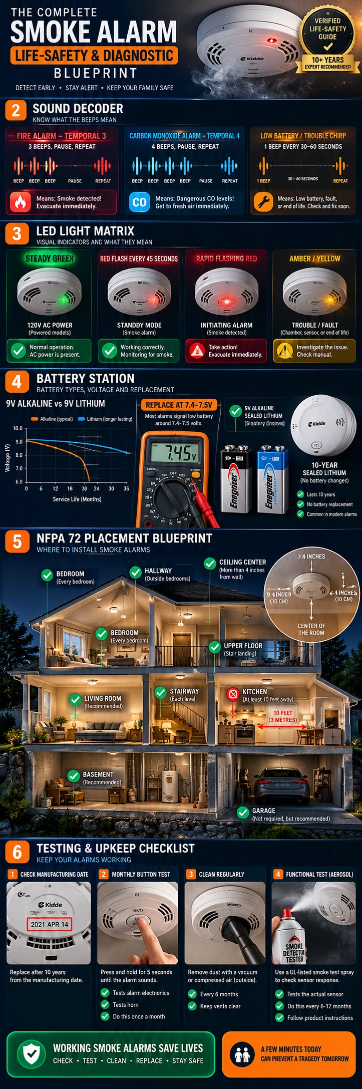
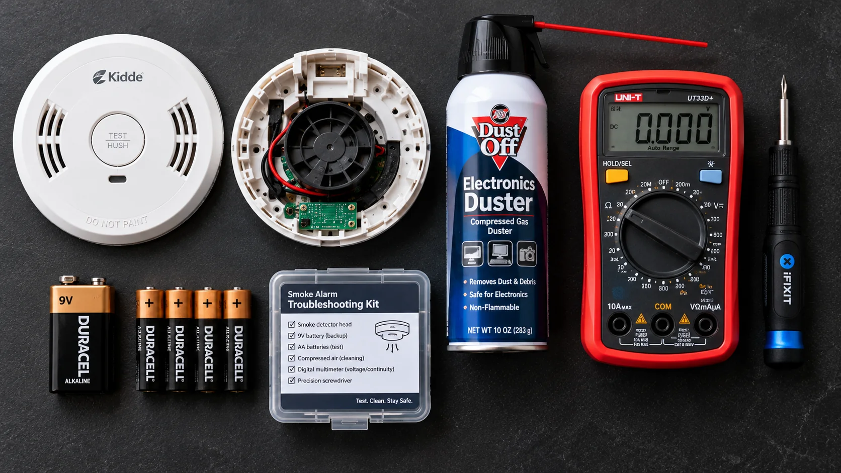
Troubleshooting a nuisance smoke alarm requires systematic field diagnostics to differentiate between active combustion events, environmental interference, electrical line noise, battery voltage decay, and 10-year sensor expiration. Modern microprocessor-controlled alarms communicate specific trouble states through coordinated audible cadences and LED strobe sequences under NFPA 72 Chapter 14.
Audible Signal Diagnostic Reference
National fire safety standards establish strict acoustic and visual signatures so occupants can rapidly identify hardware conditions:
| Audible Pattern | Underlying Hardware Condition | Diagnostic LED State | Immediate Field Action |
|---|---|---|---|
| 1 chirp every 30 to 60 seconds | Low backup battery voltage (< 7.5V DC) or AC power drop | Red LED flashes with chirp; green LED unlit if AC lost | Replace battery with industrial alkaline cell; verify AC breaker |
| Continuous 3-pulse horn (Temporal 3) | Active combustion particles detected in optical chamber | Rapid flashing red LED (1 to 4 pulses per second) | Evacuate structure if smoke exists; press Hush if cooking nuisance |
| Continuous 4-pulse horn (Temporal 4) | Toxic carbon monoxide gas detected (> 30 PPM) | Pulsing red or blue light ring; digital PPM display active | Evacuate all occupants to fresh air immediately and call 911 |
| Chirping continues after battery swap | Microprocessor capacitors holding residual trouble latch | Erratic red or amber LED flashes | Perform 20-second Test button capacitor drain with power off |
| 2 quick chirps every 30 to 45 seconds | Optical darkroom contamination or sensor calibration drift | Amber or yellow LED flashes every 10 to 15 seconds | Clean chamber with vacuum and compressed air; replace if aged |
| 3 quick chirps every 30 to 60 seconds | Hardware end-of-life non-volatile timer expiration | Red LED flashes 3 times in synchronization with chirps | Replace complete alarm; 10-year operational timers cannot be reset |
Electrical Diagnostic Standards (Hardwired Systems)
For hardwired 120V AC systems, intermittent chirping or nuisance false alarms can stem from line voltage sags, loose junction box splices, or floating neutral lines. Under US Fire Administration guidelines, mains electrical testing and panel wiring must be performed by a qualified licensed electrician. Qualified technicians verify circuit integrity against these benchmarks:
- Line Voltage (Black to White): Technicians verify line voltage measures between 110V AC and 125V AC. Voltage sags below 105V AC can cause internal power supplies to drop out, triggering repeated backup battery trouble chirps.
- Neutral to Ground Integrity: Voltage between the White neutral and grounding conductor should measure less than 2.0V AC. Readings exceeding 3.0V AC indicate high-resistance floating neutral conditions that can induce false alarms across interconnected lines.
- DC Interconnect Traveler (Red/Orange to White): In standby mode, the traveler line maintains 0.0V DC to 0.5V DC. Continuous voltage over 4.5V DC indicates an alarm on the network is actively initiating, or electromagnetic induction is bleeding voltage onto the signal conductor.
Homeowner Electrical Safety Warning: Never insert metal probes into energized ceiling junction boxes or attempt live 120V AC electrical testing yourself. Turn off branch circuit breakers at the service panel and retain a licensed electrician for all hardwired line voltage diagnostics.
How to Isolate False Alarms in Interconnected Networks
In hardwired or RF wireless networks, when one detector trips, all interconnected alarms sound simultaneously. To isolate the initiating unit:
The Initiator Isolation Protocol:
- Locate the Rapidly Flashing Red LED: Walk through every room while the horns sound. The initiating alarm is the only unit displaying a rapid red LED flash (1 flash per second or 4 rapid strobes). All other units display a solid green light with no red LED.
- Press Hush on the Initiator: Pressing the Hush button on the initiating unit silences the entire home network. Pressing Hush on follower units does nothing.
- Inspect Chamber and Clean: Dismount the initiating unit, vacuum its sensing labyrinth, and perform a 20-second capacitor drain reset.
Correcting Bent Terminal Contacts and Red Lockout Arms
Physical battery compartment defects account for a large percentage of phantom chirps:
- Bent 9V Snap Prongs: After multiple battery replacements, circular female snap terminals widen, creating loose contact resistance. With the battery removed and power disconnected, use needle-nose pliers to gently squeeze the female split prongs inward by 0.5 millimeters to ensure tight physical clamping force.
- Red Safety Lockout Arm: First Alert and Kidde units include a red plastic lockout lever inside the battery drawer. If the replacement battery is not pressed completely flat, this lever prevents the drawer from closing flush, keeping the tamper microswitch open. The alarm perceives no battery is installed and chirps every 30 seconds. Press the battery down until the red tab lays completely flat and the drawer clicks shut.
10-Year End-of-Life Replacement Requirements
Under NFPA 72 Section 14.4.7, smoke alarms have an engineered lifespan of 10 years from the date of manufacture. Over ten years, optical sensing diodes accumulate microscopic dust films and infrared emitters degrade in lumen output, increasing the probability of catastrophic failure during a real fire.
Inspect the manufacture date printed on the rear sticker. If the unit is 10 or more years old, replace the entire alarm immediately. Modern UL 217 9th Edition alarms feature advanced polyurethane and cooking nuisance resistance, significantly reducing traditional cooking and steam nuisance alarms under UL 217 8th and 9th Edition standards.