When a smoke alarm repeatedly sounds full emergency sirens without active combustion or visible smoke, systematic field troubleshooting isolates whether the trigger is optical chamber contamination, nighttime humidity shifts, furnace pyrolysis, or hardwired interconnect line surges.
How to Identify the Initiating Alarm in an Interconnected System
In hardwired residential systems wired under NFPA 72, an interconnect signal line (typically a red or orange 14 AWG traveler wire) causes every alarm in the house to sound simultaneously when a single device detects an event. Homeowners often struggle to find which unit is malfunctioning because five or six alarms are screaming at 85 decibels at the same time.
Use the front panel diagnostic LEDs to locate the source:
The Latching LED Rule:
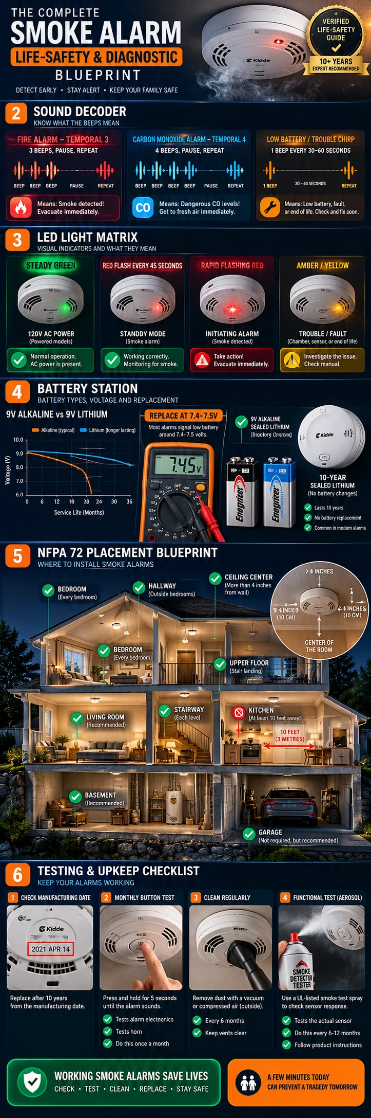
- The Initiating Alarm (Culprit): Flashes a rapid red LED (flashing once every 1 second or 4 times per second) while the horn is sounding. After silencing, it maintains a unique latching red flash pattern for up to 24 hours.
| Device Role in Loop | Visual Optical LED State | Interconnect Line Status | Troubleshooting Action |
|---|---|---|---|
| Initiating Unit (Trigger) | Rapid Flashing Red (1 Hz to 4 Hz) | Pulls 9V DC traveler wire HIGH to trip network | Press Hush button directly on this unit to silence entire home |
| Secondary Remote Units | Solid Green AC or LED unlit | Receives 9V DC input from traveler line | Do not adjust. Will silence automatically once initiator resets |
| Compromised Traveler Wire | Multiple units flashing red sporadically | Inductive AC voltage leak (> 3V DC on traveler) | Isolate traveler wire at junction box; test with digital multimeter |
The 5 Real-World Causes of Random False Alarms
1. The 3:00 AM Temperature and Humidity Inversion
A universal pattern reported by homeowners is false alarms triggering between 2:00 AM and 5:00 AM. This is governed by two physical laws:
- Temperature Drop: Overnight thermostat setbacks lower ambient room temperatures. In cold air, chemical kinetics inside alkaline backup batteries slow down, reducing terminal voltage. If the battery was already marginal, voltage drops below the 7.5V reference line during nighttime cold cycles.
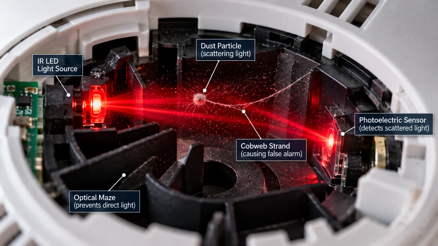
- Microscopic Dust Swelling: As room temperature drops, relative humidity rises because cooler air has a lower saturation point. Microscopic dust particles and drywall residue that have rested harmlessly inside the optical sensing darkroom absorb this ambient moisture. As the particles swell in volume, they cross the 1.5% to 2.5% obscuration threshold, deflecting infrared light into the photodiode and triggering a full fire siren.
2. Seasonal Heating Startup Pyrolysis
When a central furnace, heat pump auxiliary strip, or radiator is turned on for the first time in autumn or winter, months of accumulated household lint, pet dander, and dust burn off the combustion heat exchangers.
This heating process releases microscopic combustion particulates (pyrolysis aerosols) invisible to the human eye. These ultrafine particles quickly rise toward ceilings via thermal buoyancy. Ionization smoke alarms (which utilize an americium-241 radioactive source) are hypersensitive to microscopic particulates in the 0.01 to 0.3 micron range and trigger false alarms immediately.
3. Bathroom Steam Boundaries
Hot showers generate water vapor droplets between 5 and 10 microns in size, identical in optical reflection properties to combustion smoke. Under NFPA 72 Section 29.8.3.4, smoke alarms must be mounted a minimum of 36 inches (3 feet) horizontally from bathroom doors containing showers or tubs. If your hallway alarm sits within 10 feet of a bathroom without an active exhaust fan, high moisture drafts will trip photoelectric sensors.
4. Insect and Spider Intrusion
Smoke alarms contain dark, warm internal chambers that attract tiny spiders, thrips, and fruit flies. When an insect crawls into the light path of an optical photodiode or bridges the high-voltage ion plate gap, it mimics 100% smoke density, sending the horn into full continuous alarm.
5. Hardwired Interconnect Voltage Spikes (Floating Neutrals)
On 120V hardwired circuits, the 9VDC interconnect line (red or orange traveler wire) runs alongside standard AC conductors inside Romex cable. Large inductive household appliances (refrigerator compressors, HVAC air handlers, power tools, washing machine spin cycles) can induce transient electromagnetic spikes onto an unshielded traveler wire.
If a neutral wire nut inside a junction box is loose or corroded (a floating neutral), voltage spikes exceed the 4.5V DC threshold required to trip the interconnect bus, causing all alarms across the home to sound a brief 2-second burst or a full false alarm.
Step-by-Step Field Resolution Sequence
- Isolate and Silence: Locate the initiating alarm by finding the unit with the rapidly flashing red LED. Press its Hush button for 2 seconds to initiate an 8-minute silence pause.
- Clean the Sensing Labyrinth: Twist the initiating alarm from the ceiling, disconnect the AC plug, and remove the battery. Use a vacuum with a soft horsehair brush to clean the intake slots, followed by short bursts of clean compressed air at a 45-degree angle.
- Professional Junction Box Verification: For recurring hardwired false alarms across interconnected units, retain a licensed electrician. Qualified technicians shut off branch circuit power, drop the ceiling bracket, and inspect wiring splices inside the junction box, confirming solid connections on hot, neutral, and traveler lines without live electrical hazard to occupants.
- Check Age and Replace if Over 10 Years: Verify the date code on the rear label. If the unit exceeds 10 years of service, its optical diodes have drifted out of factory calibration and will continue to false alarm. Replace the unit with a modern UL 217 9th Edition alarm.